crystod (main command)#
The main command performs the SALC (symmetry-adapted linear combination)
analysis of crystal orbitals — no mode flag is needed. It also hosts the
crystal-orbital diagram (--diagram, with the band structure and DOS of the
same calculation), the interactive SALC viewer (--visualize) and the
star-of-k display (--star-of-k).
I want to … |
command |
|---|---|
know which irreps an orbital spans at every k point |
|
know which orbitals may hybridize at one k point |
|
draw the crystal-orbital diagram |
|
see the SALCs in 3D |
|
list the arms of a star of k |
|
1. Theoretical background#
See also
Theory: 1. Theoretical background — the
representation matrices, the character/reduction formula and the projection
operator on which every command of this page (and of crystod-group /
crystod-mag) is built.
2. Irreps of SALC#
Example directory: example/02_salc (testsuite section 2)
Decompose the crystal orbitals built from a selected element/orbital into the irreducible representations of the little group at each special k point:
crystod -c example/test_POSCARs/221_PPOSCAR_SrTiO3 --element Ti --orbital d
 * Crystal Orbitals *
 k point (primitive):  GM [0.0, 0.0, 0.0]
 little group of k  :  Pm-3m (221)
 irreps             :  1.0 [GM3+(2)] + 1.0 [GM5+(3)]

 k point (primitive):  R [0.5, 0.5, 0.5]
 little group of k  :  Pm-3m (221)
 irreps             :  1.0 [R3-(2)] + 1.0 [R4-(3)]

 k point (primitive):  X [0.0, 0.5, 0.0]
 little group of k  :  P4/mmm (123)
 irreps             :  1.0 [X2-(1)] + 1.0 [X3-(1)] + 1.0 [X4-(1)] + 1.0 [X5-(2)]

 k point (primitive):  M [0.5, 0.5, 0.0]
 little group of k  :  P4/mmm (123)
 irreps             :  1.0 [M1+(1)] + 1.0 [M3+(1)] + 1.0 [M4+(1)] + 1.0 [M5+(2)]
When --kpoint is omitted, all special k points of the space group are analyzed.
Any arm of a special-point star is labeled correctly.
--show-irrep-table additionally prints the little-group character table at the
selected k point.
3. Crystal-orbital diagrams#
Example directory: example/03_hybridization (testsuite section 3)
Analyze the hybridization between selected atomic orbitals (ELEMENT_ORBITAL pairs):
crystod -c example/test_POSCARs/221_PPOSCAR_ScF3 --atomic-orbital Sc-d F-p --kpoint 0.5 0.5 0.5
 * Result *
 R1+(1): F(p)
 R1-(1):
 R2+(1):
 R2-(1):
 R3+(2): Sc(d) F(p)
 R3-(2):
 R4+(3): F(p)
 R4-(3):
 R5+(3): Sc(d) F(p)
 R5-(3):
For each little-group irrep at the k point, the orbitals that transform as the relevant irreps are listed — orbitals sharing a line are symmetry-allowed to hybridize. We can see that Sc-d and F-p states can be hybridized when they are ruled by the irreps of R3+ and R5+.
Quantitative crystal-orbital diagrams using extended-Hückel engine (--diagram)#
--diagram draws the quantitative crystal orbital diagram (COD) — the
crystalline analogue of the molecular-orbital diagram of
crystod-mol --diagram --ao-left ... --ao-right ....
--co-left/--co-right split the crystal into two fragment sublattices by
chemical formula (every atom must belong to one side; a count such as O3
validates against the primitive cell).
Each fragment carries its full-electron basis — every core and valence
shell of every atom: core shells with Slater-rule Slater-type orbital (STO)
exponents, valence shells with the extended-Hückel parameters, and the level
energies from the archived neutral-atom PySCF calculations
(reference/atomic_level_{El}, one Hartree-Fock/def2-svp run per element).
Each fragment then feels the removed sublattice as a point-charge lattice
with the formal oxidation states (guessed with pymatgen; override with
--oxidation Sr=+2 Ti=+4 O=-2): the Sc fragment of ScF3 sits in the field
of the F lattice with Q = -1, the F3 fragment in the field of the Sc
lattice with Q = +3 — the Madelung ligand field of the pre-bonding states:
crystod --diagram -c 221_PPOSCAR_ScF3 --co-left Sc --co-right F3
# -> CrystOD_221_PPOSCAR_ScF3.html
The terminal prints, per k point, the two fragment columns and the crystal orbitals with their irrep, degeneracy, occupation and composition — at R the textbook perovskite pattern:
 * k point R (1/2,1/2,1/2) *
   Sc        : ... Sc 3d R5+ (-9.08), Sc 3d R3+ (-7.62), ...
   F3        : ... F 2p R1+ (-19.67), F 2p R3+ (-19.33), F 2p R5+ (-17.56), F 2p R4+ (-17.30)
   crystal   :
     ...
     R3+ #1        -19.46 eV  x2  4e   F 2p R3+ 93.5%  Sc 3d R3+ 6.5%
     R5+ #1        -17.70 eV  x3  6e   F 2p R5+ 95.4%  Sc 3d R5+ 4.6%
     R4+ #1        -17.30 eV  x3  6e   F 2p R4+ 100.0%
     R5+ #2         -8.18 eV  x3       Sc 3d R5+ 95.4%  F 2p R5+ 4.6%
     R3+ #2         -5.21 eV  x2       Sc 3d R3+ 93.5%  F 2p R3+ 6.5%
At every special k point CrystOD symmetry-adapts the Bloch orbitals of both
fragments, evaluates every intra- and inter-fragment overlap as an exact STO
lattice sum, adds the point-charge ligand field and solves the resulting
Wolfsberg-Helmholz eigenvalue problem. Fragment orbitals sharing an irrep
split into bonding and antibonding crystal orbitals; orbitals without a
same-irrep partner stay rigorously nonbonding — the COD mixing rule. In the
table above the eg-derived R3+ pair splits strongly (σ / σ*), the t2g-derived
R5+ pair weakly (π / π*), and R4+ has no Sc partner at all and remains
100 % F 2p.
The written HTML is the diagram below — the live output of the command, one energy diagram per k point (the buttons switch k), fragment | crystal | fragment columns with correlation lines weighted by the composition, electron arrows and HOMO/LUMO markers. Hover any level for its wave-function sketch (all atomic-orbital components on the k-commensurate supercell, VESTA-style +/- lobes, drag-rotatable):
Open the ScF3 crystal-orbital diagram full-screen
Options: --electrons N overrides the electron count (default: all electrons
of the neutral atoms); --kpoint GM restricts the diagram to one special
point; --conventional draws the hover sketches in the conventional cell;
--output/--tolerance as usual. Elements H-Bi of the standard
extended-Hückel tables are parameterized.
The page itself keeps every k point, and the one it opens on can be chosen in
the URL — CrystOD_POSCAR.html?k=R (or #R) — which is what the embedded
diagram above does. That makes a single file embeddable anywhere in the star
without regenerating it; the k buttons still switch freely afterwards.
See also
Theory: How the orbital diagrams are computed — the symmetry-adapted Bloch basis, the exact STO lattice sums, the Ewald point-charge ligand field, the overlap-catastrophe cut-off and their validation.
Quantitative crystal-orbital diagrams using PySCF (--diagram --pyscf)#
--pyscf replaces the extended-Hueckel model by three periodic PySCF
calculations that share one atomic-orbital space — the crystalline
counterpart of crystod-mol --diagram --pyscf. It needs the optional PySCF
dependency, pip install "CrystOD[quantum]" (see Installation);
without it the run stops with a one-line ERROR: naming this command.
crystod --diagram -c 221_PPOSCAR_ScF3 --pyscf --co-left Sc --co-right F3
crystod --diagram -c 221_PPOSCAR_SrTiO3 --pyscf --co-left SrTi --co-right O3
# -> CrystOD_{cell}_pyscf.html
calculation |
real atoms |
point charges |
|---|---|---|
left fragment |
the |
the right sublattice |
right fragment |
the |
the left sublattice |
crystal |
everything |
none |
The removed sublattice stays in the basis as ghost atoms and at the same
time acts on the fragment as its formal-charge point lattice
(--oxidation Sc=+3 F=-1 overrides the guessed oxidation states), so all
three calculations span one AO space (counterpoise-consistent) and each
fragment is one sublattice in the Madelung field of the other — the
electronic state before chemical bond formation. Every cell is neutral, but
each calculation still pins its own cell-averaged potential, so the raw
columns are offset by one rigid, k-independent constant each; the diagram
removes it by deep-level (XPS-style) alignment against the deepest
chemically inert fragment level (printed with anchor, purity and k-spread),
and --no-align keeps the raw references instead.
--oxidation Al=0 N=0 switches the model to neutral-atom sublattices
(the extended-Hückel engine’s convention): the point-charge lattice then
vanishes, and a sublattice with an odd electron count per cell (neutral
Al: 3) is solved spin-restricted with Fermi smearing — the run says so,
and --sigma sets the width (default 0.2 eV for such cells; integer aufbau
would silently drop the unpaired electron). The isolated-atom columns pick
their ground spin state by scanning the parity-consistent spins and keeping
the lowest energy — a neutral N atom takes the Hund spin-3 ⁴S state, not a
spin-1 doublet. Open-shell atomic columns display the alpha channel
(said in the tooltip); for main-group atoms the alpha inter-shell spacings
match the spin-averaged ones to ~0.1 eV, but for high-spin d/f atoms the
exchange splitting can shift them by ~1 eV against the spin-restricted
sublattice reference.
Crystal-orbital lines are colored by bonding character (blue = bonding,
black = nonbonding, red = antibonding) from the COOP-style left-right overlap
population of each eigenstate, and the fragment columns are drawn in the VESTA
color of each level’s dominant element. Degeneracies are exact by
construction: all displayed levels are re-diagonalized from the group-averaged
Fock, whose invariance under the AO representation is verified against PySCF’s
own overlap matrix (D+ S D = S, residual printed per k point).
Main options: --basis (default gth-dzvp-molopt-sr), --pseudo (default
gth-pbe), --xc (default pbe, or hf), --ke-cutoff (default 200
Hartree), --kmesh (default round(8 A / |a_i|)), --max-l L (drop basis
shells above l = L), --projection lowdin|mulliken, --no-ghost,
--no-symmetrize, and --chk (below). The same-irrep resonance-integral
tables are written to <output-stem>_coupling.txt next to the HTML.
Because a three-SCF --pyscf run is expensive, the converged densities are
cached automatically as CHK_{formula}.chk (rutile TiO2: CHK_TiO2.chk,
the reduced formula in conventional chemical order). The next run on the same
structure with the same options reads it and skips all three SCFs; a run whose
options differ says so and recomputes, overwriting the file. --chk FILE
keeps the strict behaviour instead: that file is yours, so a parameter
mismatch aborts with crystod --chk-info guidance rather than overwriting it.
crystod --help lists every value these take. The short version — of the
GTH basis sets PySCF ships, only gth-szv-molopt-sr and
gth-dzvp-molopt-sr cover the transition metals and beyond (H–Rn, with
the lanthanides La–Lu absent from every GTH set, so --pyscf cannot run
on a rare-earth compound at all — the extended-Hückel engine can); the
larger sets (gth-tzvp, gth-qzv2p, the gth-aug-* and gth-cc-*
families, …) stop at Ar or cover a handful of light elements, so they buy
diffuse and polarization freedom only for main-group compounds. A basis or
pseudopotential without an entry for one of the elements is refused with the
list of sets that do cover the structure. For --pseudo, gth-pbe,
gth-pade (LDA), gth-lda and gth-hfrev span H–Rn, gth-blyp reaches
Bi, and the rest are light-element only. --xc accepts most libxc names (a name libxc does not know, and a VV10
functional such as wb97m-v — PySCF’s periodic code has no nonlocal
correlation — are both refused up front with the reason);
LDA (lda, svwn), GGA (pbe, pbesol, revpbe, blyp, bp86,
pw91, b97-d), meta-GGA (scan, r2scan, tpss, revtpss) and
hybrids (b3lyp, pbe0, hse06, m06, wb97x, …) all run here, plus
hf for Hartree–Fock; hybrids evaluate exact exchange on the FFT grid, so
give them --ke-cutoff 150 or more.
--onsite — the single-Hamiltonian diagram. Only the crystal SCF runs, and
the fragment columns are the per-(element, shell) on-site multiplets of the
converged crystal Fock — one level per induced irrep, no point charges and no
alignment step, so a crystal level’s drop or rise against its parent is the
orbital interaction:
crystod --diagram -c 225_PPOSCAR_NaCl --pyscf --onsite --co-left Na --co-right Cl \
    --kpoint X --kmesh 1 1 1 --ke-cutoff 80
See also
Theory: How the orbital diagrams are computed
— the counterpoise (ghost-atom) construction, the neutrality bookkeeping, how
the deep-level alignment anchor is chosen, and why --onsite takes the
fragment columns from the crystal Fock.
Quantitative crystal-orbital diagrams from VASP (--diagram --vasp)#
--vasp builds the same three columns from finished VASP runs instead of
from an internal SCF: the crystal run supplies the middle column, and two
sublattice runs — each keeping one sublattice and replacing the other by
classical point charges — supply the two fragment columns. Nothing is
computed here; CrystOD reads POSCAR, PROCAR (LORBIT = 12) and a handful
of OUTCAR facts from each directory (gzipped files are accepted).
crystod --diagram [-c POSCAR] --co-left SrTi --co-right O3 --vasp-setup [ROOT]
#   writes ROOT/BAND_sublattice1 and ROOT/BAND_sublattice2 (POSCAR, KPOINTS,
#   INCAR, POTCAR) and prints the three run commands
crystod --diagram --co-left SrTi --co-right O3 --vasp                 [ROOT]
#   -> CrystOD_{formula}_{space group}_vasp.html + _levels.txt + _levels.json
crystod --diagram -c POSCAR --co-left SrTi --co-right O3 --vasp       [ROOT]
#   -> CrystOD_{cell}_vasp.html  +  CrystOD_{cell}_vasp_levels.txt
#      +  CrystOD_{cell}_vasp_levels.json (the same content, machine-readable)
directory |
column |
real atoms |
removed sublattice |
|---|---|---|---|
|
crystal |
everything |
— |
|
either |
its own real species |
|
|
either |
its own real species |
|
The forms of --vasp. It takes no path (the current directory is the
ROOT), one ROOT with the three directories of the table above, or the
three run directories in any order — whatever they are named and wherever
they live:
crystod --diagram --co-left SrTi --co-right O3 --vasp .
crystod --diagram --co-left SrTi --co-right O3 \
        --vasp ./BAND ./BAND_sublattice1 ./BAND_sublattice2
With three paths the crystal run is the one whose POSCAR carries no Va
species, and the order they are given in makes no difference to the output.
Two paths, or more than three, are refused in one line that shows the accepted
forms. DIR/band is used when it carries the PROCAR. Which sublattice
directory is the left and which the right column is decided from the real
(non-Va) elements of its POSCAR, never from the number in its name;
--vasp-crystal DIR --vasp-left DIR --vasp-right DIR override any one column
in any of the three forms.
-c is optional, and it fixes the setting. Without it the structure is
the crystal run’s own POSCAR. With it, the analysis is done in the primitive
cell of that file — so the irreps agree level for level with the other engines
and with crystod -c FILE --element … --orbital … on the same file — and each
run is mapped onto that setting: one global origin shift, a permutation of
the atoms and lattice-vector wraps, with Va atoms mapping onto the removed
ones. The run’s lattice matrix has to be the -c primitive one within a
relative 1e-3. A -c file with Sr at the origin and runs written with Ti
there is therefore the same analysis, not an error:
crystod --diagram -c POSCAR-finish --co-left SrTi --co-right O3 --vasp .
#  * Setting *
#   ./BAND/POSCAR = the -c cell shifted by (1/2, 1/2, 1/2);
#   atom order Sr Ti O O O -> Sr#1 Ti#2 O#5 O#3 O#4
#   irrep labels refer to the POSCAR-finish setting
The mapping is stated in the terminal report, in the level table, in the JSON
("setting") and as a chip on the page whenever it is not the identity:
irrep labels at R, X and M depend on the choice of origin, so it matters
which file they belong to. The energies, the projected weights, the site
shifts and the connector weights do not — they are the same numbers in either
setting. If the -c file and the crystal run are the same crystal in
genuinely different bases, the analysis falls back to the crystal run’s own
setting and says so; if they are not the same crystal, the run stops with one
line naming what differs and suggesting -c BAND/POSCAR.
--vasp-setup writes in the crystal run’s setting. -c is optional there
too: without it the structure is ROOT/BAND/POSCAR. With it, the -c file
names the fragments and fixes the formal charges, but the POSCARs that are
written always follow the crystal run’s own cell, origin and ion order —
they are ROOT/BAND/POSCAR with one sublattice renamed to Va<q><sign>, line
for line. The assignment travels there through the same mapping --vasp uses,
and the setting is printed ( setting : …). Otherwise the two fragment
runs would sit on another origin — and, through the -c file’s own lattice
constant, on a slightly different cell — than the crystal run they are
compared with. A -c file that is not the crystal run’s cell in another
setting stops --vasp-setup in one line suggesting -c BAND/POSCAR.
A run directory that already holds a finished calculation (OUTCAR,
PROCAR or vasprun.xml) is not rewritten: --vasp-setup stops in one
line naming the directory and the files, because the INCAR it would write is
not the INCAR that was run. --force overwrites anyway.
Names. With an ordinary -c file the page is CrystOD_{cell}_vasp.html,
as in the other engines. Without -c, or when the -c file lives inside one
of the run directories, the name comes from the composition and the space
group — CrystOD_SrTiO3_Pm-3m_vasp.html, titled SrTiO3, Pm-3m — so that it
is never the run directory’s BAND.
The point-charge sublattices. A sublattice run names its switched-off
atoms Va<q><sign> (Va2-, Va4+) — a species of a modified VASP that
represents them as a smeared Coulomb charge plus a short repulsive wall, the
wall standing for the Pauli repulsion of the removed ion’s core, as in
total-ion-potential embedding. The formal charges come from CrystOD’s own
oxidation-state resolution (--oxidation), so the cell stays neutral and each
fragment is one sublattice in the Madelung field of the other. VASP itself is
proprietary and is not distributed with CrystOD; the patch that adds the Va
species is available to VASP licensees on request. --vasp itself needs no
patched VASP — it only reads the output files.
The wall is what a point charge needs to stop being a bare −q/r well, and it
is calibrated: --vasp-setup writes VACSIGMA 0.5, VACRWALL 0.45 and
VACWALL = 2.5 q e²√(2/π)/σ (--vasp-sigma, --vasp-rwall,
--vasp-wall-factor change them; one height is written per Va species, so
the charge scaling stays automatic). A 72-point scan on SrTiO₃ and ScF₃ shows
the whole family organized by one coordinate, the radius r₁₀ = b√(2 ln(A/10 eV)) at which the wall still repels by 10 eV: below 0.7 Å the anion
sublattice collapses into the bare well (bands below the projection floor,
metallic points), above 1.4 Å the wall expels the anion valence shell (an O 2p
manifold three times too wide). The setting above sits at r₁₀ = 0.99 Å for
q = +2 and 1.13 Å for q = +4 — the middle of the 0.85–1.25 Å plateau, one
setting for every charge — and is the joint minimum of the anchor-residual rms
on both test systems while matching the crystal’s anion p-manifold width to
0.1 eV. Fluorite CaF₂, a third space group with a tetrahedral anion cage,
transfers without retuning. What the wall chooses is the anion column’s
position: over the whole scan the shift ranges over 45 eV while the
residual rms on the plateau moves by 0.1 eV.
Irreps from the projections. A LORBIT = 12 PROCAR lists the complex
projections ⟨Y_lm at atom | ψ_nk⟩. CrystOD treats that vector as a vector in
an AO-like (atom, l, m) basis and classifies it with the same representation
matrices and character projectors it builds for a genuine AO basis — the
Bloch-phased site permutation times the real Wigner matrices, with no
further gauge conjugation, because the PROCAR coefficients are already in
that Bloch gauge — after reordering VASP’s m = −l..l rows into its own
component order. Degenerate
bands are grouped adaptively until the irrep multiplicities come out integral.
The result is checked against the site-symmetry induced representation
(the SALC decomposition the report prints for every element and shell), and a
level whose best irrep weight falls below 0.9 is listed in a purity warning.
PAW sphere projections do not sum to one, so levels whose projected weight per
degenerate partner falls below --vasp-projection-floor (0.30) are
free-electron-like and are dropped; the report prints the weights bracketing
the cut.
Alignment. Each of the three runs pins its own G = 0 average potential to
zero, so the raw columns are offset by one constant each. The crystal column
is the reference (shift 0) and every fragment level is raised onto it by a
site-resolved shift: one constant per (column, element), because the
shells of one atom move together but different sites do not — a cation that
receives covalent back-donation in the crystal has all its levels raised by the
intra-atomic Coulomb repulsion the bare-point-charge fragment lacks (on SrTiO₃
the Ti site moves 11.7 eV more than the ionic Sr site). Each element’s shift is
fitted to the symmetry-forbidden probes alone wherever it has any — fragment
levels whose irrep has no partner in the other sublattice at that k, which
therefore must coincide with their crystal counterpart, an exact constraint.
The pure XPS-style counterparts (absolute composition ≥ 0.80) are then
reported as what they are, the measured bonding shift of each pair, instead of
being averaged into the scale; an element with no forbidden probe (CaF₂ Ca) is
fitted to them and flagged, because their residuals average to zero by
construction. The anchor pool is
cut at the default window, never at --vasp-window, so the drawn range
cannot move the energy scale. The report lists every anchor, the per-shell
means, the spread per element and the site-potential difference between the
elements of one column, plus an independent occupied-band trace diagnostic
that uses no projection at all. --vasp-zero vbm|efermi|raw sets the energy
zero of the page and the tables (default E − E_VBM, the VBM being the highest
occupied crystal eigenvalue over all k of the crystal run). --vasp-align rigid falls back to one shift per column (whose numbers are printed as a
diagnostic in either mode), --vasp-anchor EL nl pins a column on a shell of
your choice — and selects rigid, since that is what it means — and
--no-align keeps the raw VASP energies.
Bond character. A plane-wave calculation has no overlap matrix, so there is no COOP population to quote. The character is read from the aligned energies instead: a crystal level carrying 95 % or more of its projected weight on one sublattice is nonbonding; otherwise it is bonding when it lies below, and antibonding when it lies above, the composition-weighted energy of the fragment levels its connectors point at (0.3 eV deadband, quoted beside the alignment residual the run itself measures — the centre-of-gravity sum rule over every complete (k, irrep) manifold, 0.59 eV mean on SrTiO₃ and 0.19 eV on CaF₂ — so a colour inside the noise says so). A level with a parent on an element whose own anchors disagree by more than 1 eV keeps the neutral grey stroke, and so does one whose drawn parents hold less than half of it or whose character would change if the levels the window hides were drawn: one shift does not describe that site, so the sign of E − E(parents) carries no chemistry there. With bare point charges that happens on the site whose shells disagree most — on SrTiO₃ the Sr site, whose empty, diffuse 4d shell sits 1.5 eV away from what its own semicore says.
 * Site-resolved alignment (reference = the crystal column, shift 0) *
   energy zero: E - E_VBM  (VBM 2.604 eV, highest occupied crystal eigenvalue over all k of the crystal run)
   left  SrTi   (column mean +7.658 eV)
     Sr  delta =   +3.530 eV   14 anchors (5 symmetry-forbidden), shell spread 1.26 eV -> NOT one scale (> 1 eV)
     Ti  delta =  +15.255 eV   8 anchors (2 symmetry-forbidden), shell spread 0.00 eV -> shells agree
        fitted to the symmetry-forbidden probes ALONE
        Ti 3d     +16.131  n=8  spread  2.95  *
        symmetry-forbidden probes only: +15.255 eV (n=2, spread 0.15 eV); after the shift they close to 0.078 eV
          GM   Ti 3d GM5+       forbidden w=0.983 -> GM5+ #1       +15.177 eV   closes to -0.078
          GM   Ti 3d GM3+       pure      w=0.949 -> GM3+ #2       +17.152 eV   bonding shift +1.897
     Ti - Sr: +11.73 eV -- the site-potential change between the point-charge model and the
          self-consistent crystal
   right O3   (column mean +6.147 eV)
     O   delta =   +6.091 eV   14 anchors (2 symmetry-forbidden), shell spread 0.12 eV -> shells agree

 * Measured alignment residual (centre of gravity of every complete (k, irrep) manifold) *
   22 complete manifolds: mean |residual| 0.594 eV, max 1.248 eV (M M4+, +1.248 eV)

 * k point R (1/2,1/2,1/2) *
   site-symmetry induced representations (SALC decomposition):
     Ti 3d   = R3+ + R5+
     O 2p    = R1+ + R3+ + R4+ + R5+
   crystal   :
     R3+ #1         -4.18 eV  x2  4e   Ti 3d R3+ 50.5%  O 2p R3+ 49.5%
     R5+ #2         -3.73 eV  x3  6e   O 2p R5+ 64.0%  Ti 3d R5+ 29.3%  Sr 4p R5+ 6.8%

CrystOD_SrTiO3_Pm-3m_vasp.html for SrTiO₃ at R: the cation sublattice SrTi⁶⁺ (left)
and the anion sublattice O₃⁶⁻ (right), both computed with the removed
sublattice replaced by Va point charges, against the crystal levels in the
middle; the selected R3+ band is the even Ti 3d / O 2p mixture the excerpt
above quantifies. With the site-resolved shift the Ti 3d fragment levels sit
just below the crystal t₂g/e_g bands they mix into, and the bands are coloured
bonding / nonbonding / antibonding again; only the levels with an Sr parent
keep the neutral grey stroke.#
Main options: --vasp-align site|rigid, --vasp-zero vbm|efermi|raw,
--vasp-window EMIN EMAX (drawn range relative to the VBM,
default up to +10 eV), --vasp-projection-floor W, --vasp-anchor EL nl,
--vasp-mesh N N N and --potcar-dir / --potcar-map EL=NAME / --vasp-bin
/ --vasp-rwall / --vasp-sigma / --vasp-wall-factor for --vasp-setup. Limitations: non-spin-polarized runs
only (a spin-polarized run is refused with one ERROR: line), the three
runs must share one primitive cell with the same atom order, and every
share and connector weight is a PAW-sphere projection, which is blind to
the radial channel — a semicore and a valence shell of the same (atom, l) are
not orthogonal in it, so the shares and the connectors are resolved by the
PAW valence n of each channel (a Sr 5s share can never be handed to the
Sr 4s semicore level) and a channel with no fragment level on the page is
dropped rather than re-routed.
See also
example/03_hybridization/vasp_SrTiO3/ holds a trimmed copy of the three
SrTiO₃ runs (the four special k points only) that reproduces every number
above offline, and example/03_hybridization/vasp_CaF2/ the same for
fluorite. CaF₂ is there for a reason: its F sites sit on quarter coordinates
of the primitive basis, where the PROCAR’s Bloch gauge can be tested, and it
is the ionic control of the site-resolved alignment — Ca +4.54 and F +4.42 eV
move together to 0.1 eV, against 11.7 eV between Ti and Sr in SrTiO₃.
Band structure, fatbands and DOS (--band, --dos)#
Before zooming into the special k points with the diagram, read the whole band
structure. --band diagonalizes the recorded density matrix
non-self-consistently along the automatic seekpath path (the VASP-style
two-step; with a matching --chk no new SCF is run), and --fatband adds the
element- and (element, l)-projected versions:
crystod --band --fatband --pyscf -c 221_PPOSCAR_ScF3 --co-left Sc --co-right F3 \
    --kmesh 2 2 2 --ke-cutoff 80 --max-l 2 --chk ScF3.chk
   k path : GAMMA-X-M-GAMMA-R-X  |  R-M  (242 points, 41 per leg)
   non-self-consistent bands on 242 k points ...
   VBM +0.000 eV at R, CBM +5.199 eV at GM  ->  gap 5.199 eV on this path (mesh gap 5.199 eV)
Band structure written to BAND_221_PPOSCAR_ScF3.pdf, BAND_221_PPOSCAR_ScF3_fatband.pdf, BAND_221_PPOSCAR_ScF3_fatband_Sc.pdf, BAND_221_PPOSCAR_ScF3_fatband_F.pdf, BAND_221_PPOSCAR_ScF3.csv, BAND_221_PPOSCAR_ScF3.txt
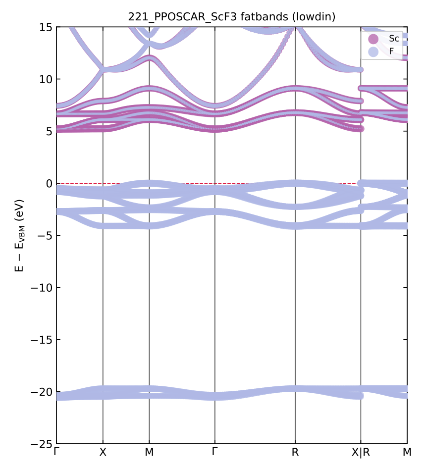
BAND_221_PPOSCAR_ScF3_fatband.pdf: the element-projected fatband overview in
VESTA colors (dot size = projected weight). The F 2p valence manifold just
below 0 eV and the isolated F 2s band near −20 eV carry no Sc weight at all,
while the conduction bands from +5 eV up pick up the Sc (red) character — the
d0 insulator whose R-point σ/σ*, π/π* splitting the diagram above resolves
level by level. Bands are referenced to the VBM (--align absolute keeps the
raw scale), and the plotted window follows --window LO HI.#
--dos is the k-integrated companion: Gaussian-broadened total DOS, element x
angular-momentum PDOS, and the partial charges in both conventions, on a dense
--dos-kmesh (default 8x8x8):
crystod --dos --pyscf -c 221_PPOSCAR_ScF3 --co-left Sc --co-right F3 \
    --kmesh 2 2 2 --ke-cutoff 80 --max-l 2 --chk ScF3.chk
 * Lowdin partial charges (sum of populations = 32.0000 electrons, expected 32) *
   Sc0: population 10.9960  net charge +0.004   (3s 1.641  4s 0.336  5s 0.140  3p 5.715  4p 0.878  3d 1.434  4d 0.852)
   F1: population  7.0013  net charge -0.001   (2s 1.523  3s 0.070  2p 5.203  3p 0.197  3d 0.008)
 * Mulliken partial charges (sum of populations = 32.0000 electrons, expected 32) *
   Sc0: population  9.4266  net charge +1.573   (3s 1.983  4s 0.054  5s 0.038  3p 5.987  4p 0.334  3d 1.064  4d -0.033)
   F1: population  7.5245  net charge -0.524   (2s 1.948  3s -0.006  2p 5.603  3p -0.022  3d 0.002)
   (an atomic partition of a continuous density is a convention: with this diffuse basis Loewdin tends toward neutral atoms, Mulliken keeps the ionic picture)
   VBM +0.000 eV, CBM +5.199 eV, gap 5.199 eV (Fermi filling on the 8x8x8 mesh)
DOS plot written to DOS_221_PPOSCAR_ScF3.pdf
Both write a PDF, a CSV of every curve (or every band energy and weight) and a
TXT summary, both accept --onsite (neither needs the fragment densities), and
both share one checkpoint with the diagram runs.
Restart files (--chk, --chk-info)#
--chk FILE is the WAVECAR analogue of the PySCF modes: the converged density
matrices and the defining parameters are saved after the SCFs, and a rerun with
the file present skips all three SCFs. The parameters are verified first, and a
mismatch aborts naming the offending option — so a diagram, a band structure
and a DOS of the same system cost exactly one SCF set in total.
--chk-info FILE prints what a checkpoint holds, ending with a ready-to-paste
option string that reproduces it:
crystod --chk-info ScF3.chk
 * ScF3.chk -- CrystOD SCF checkpoint (WAVECAR-style restart, 0.8 MB) *
   structure : Sc + F3, 4 atoms/cell, a = 4.0696 / 4.0696 / 4.0696 A
   method    : PBE / gth-dzvp-molopt-sr / gth-pbe, ke_cutoff 80 Ha, k-mesh 2x2x2, max_l 2
   electrons : 32 per cell (oxidation F=-1 Sc=+3)
   fragments : left Sc | right F3, counterpoise ghosts
   contents  : full three-SCF run; densities on 8 k points x 58 AOs
   energies  : mo -119.66022723 Ha  |  left -46.60996096 Ha  |  right -72.41588868 Ha
   smearing  : right carried Fermi smearing when written
   reuse with: --co-left Sc --co-right F3 --xc pbe --basis gth-dzvp-molopt-sr --pseudo gth-pbe --kmesh 2 2 2 --ke-cutoff 80 --max-l 2 --oxidation F=-1 Sc=+3 --chk ScF3.chk
4. Star of k#
Example directory: example/04_star_of_k (testsuite section 4)
Display the star of k: the set of inequivalent k points generated from a given
k point by the space-group rotations (k' = k R, modulo reciprocal lattice):
crystod --star-of-k -c example/test_POSCARs/221_PPOSCAR_ScF3 --kpoint 0.5 0.5 0
crystod --star-of-k -c example/test_POSCARs/221_PPOSCAR_ScF3 --kpoint M
 * Space group *
 Pm-3m (221)

 * k point (primitive) *
 M [0.5, 0.5, 0.0]

 * Star of k *
 |G| = 48, |G_k| = 16, |star of k| = 3
 arm 1: k = [+0.5, +0.5, +0]   (representative: 1)
 arm 2: k = [+0.5, +0, +0.5]   (representative: 3^+_111)
 arm 3: k = [+0, +0.5, +0.5]   (representative: 2_101)
The output shows |G|, the little co-group order |G_k|, |star of k|, and each
arm with its coset-representative operation in Seitz notation.
The star of q is also displayed automatically in crystod-phonon --modulation
for each selected q point, which is useful when combining arms of the same star
in multi-q modulations.
5. SALC basis visualization (--visualize)#
Example directory: example/05_visualized_basis (testsuite section 5)
Build the SALCs of a selected element/orbital at a k point, print the irreducible decomposition and per-atom SALC coefficients, and export an interactive 3D HTML visualization:
Example 1: Sc d orbitals of ScF3 at the R point#
crystod --visualize -c 221_PPOSCAR_ScF3 --element Sc --orbital d --bond Sc F 2.5 --real-coefficient
# -> SALC_221_PPOSCAR_ScF3_Sc_d_{GM,X,M,R}.html
 * k point (primitive) *
 R [0.5, 0.5, 0.5]

 * Irreducible Decomposition *
 1.0 [R3+(2)] + 1.0 [R5+(3)]

 * SALC basis functions (irrep-grouped) *
 Mode Space 1: irrep = R3+(2), dimension = 2
   component 1:
     Sc1 (atom 0): d_z2: +1.0000
   component 2:
     Sc1 (atom 0): d_x2-y2: +1.0000

 Mode Space 2: irrep = R5+(3), dimension = 3
   component 1:
     Sc1 (atom 0): d_xy: +1.0000
   component 2:
     Sc1 (atom 0): d_yz: +1.0000
   component 3:
     Sc1 (atom 0): d_xz: +1.0000
Open the ScF3 SALC viewer full-screen
The viewer above is the live output of the command;
the commensurate 2x2x2 supercell is built and the Bloch phase alternates the
lobe signs from cell to cell (the Sc d SALCs at R decompose as
R3+(2) + R5+(3)). Click any row of the SALC table in the sidebar to switch
the displayed basis vector, toggle the ScF6 polyhedra, and drag to rotate.
Note that the option --real-coefficient transforms the basis into physically irreducible representation.
Additionally, the option --bond Sc F 2.5 draws the coordinated polyhedra considering chemical bond Sc-F shorter than 2.5 Angstrom.
Without --kpoint one page per special k point is written, auto-named
SALC_{structure}_{element}_{orbital}_{kpoint}.html; with an explicit
--kpoint the shorter SALC_{element}_{orbital}_{kpoint}.html is used
(--output overrides either).
Example 2: Ce f orbitals of CeO2 in the conventional cell (--conventional)#
crystod --visualize -c 225_PPOSCAR_CeO2 --element Ce --orbital f --kpoint 0 0 0 --bond Ce O 3 --real-coefficient --conventional
CeO2 is face-centred (Fm-3m), so its primitive cell is the small rhombohedral
one — hardly the picture one has in mind for fluorite. --conventional
switches the display to the cubic conventional cell (four formula units, the
familiar CeO8 cube arrangement) while the SALC coefficients themselves are
unchanged. The corner compass then shows both lattices: the primitive
vectors as short pastel arrows (aprim, bprim,
cprim — the face diagonals) and the conventional vectors of the
displayed cell as full-color arrows (aconv, bconv,
cconv — the cubic axes):
Throughout CrystOD, --kpoint is given in the primitive reciprocal
basis. With --conventional the sidebar therefore lists the k point in
both bases —
k point   X [0.0, 0.0, 0.5] (primitive)
k point   X [0.5, 0.5, 0.0] (conventional)
(the X point of I4/mmm La3Ni2O7) — which says at a glance why the display needs the supercell it shows: the conventional coordinates (1/2,1/2,0) make the Bloch phases commensurate only over 2 x 2 x 1 conventional cells.
Open the CeO2 conventional-cell SALC viewer f ull-screen
--real-coefficientre-combines degenerate SALC components into real-coefficient form whenever the projected space is closed under complex conjugation (real-type irreps at k = -k points). For example, the GM3+ (Eg) SALCs of Sc_d, which are otherwise produced as(d_z2 +/- i d_x2-y2)/sqrt(2), becomed_z2andd_x2-y2. The spanned space is unchanged; only the unitary basis choice within the irrep space is rotated.--mode-index Nrestricts the output to one irrep-grouped mode space (1-based).--bond EL1 EL2 MAXis repeatable, so several bond types can be drawn at once.
The viewer layout is modeled after the phonon website by Henrique Miranda (github.com/henriquemiranda/phononwebsite, BSD-3-Clause) — CrystOD imitates its sidebar-plus-viewport design (no code is copied; the 3D rendering uses plotly).
Extended-Hückel eigen-levels in the viewer (bare --visualize)#
--visualize without --element/--orbital shows eigen-levels
instead of the basis: it runs the same symmetry + extended-Hückel engine
as crystod --diagram and writes one SALC-viewer page per special k
point — the energy levels inside the default window (HOMO−15 ..
LUMO+10 eV; --window opens the deep shells), each row a degenerate
partner, the clicked row rendering the eigenvector’s wave function:
crystod --visualize -c 221_PPOSCAR_ScF3
crystod --visualize -c 221_PPOSCAR_ScF3 --sublattice Sc --kpoint R --diagonalize
# -> SALC_eht_<structure>_<crystal|fragment>_<k>.html
No SCF and no basis options — the full-electron STO basis, the archived
atomic levels and the point-charge ligand field are all tabulated, so the
bare command works out of the box (--oxidation overrides the guessed
point charges, --electrons the filling). --sublattice Sc shows the
pre-bonding Sc-sublattice block of the shared Hamiltonian instead of the
crystal; all three views sit on ONE energy reference by construction (a
single Hamiltonian — no alignment step exists here).
PySCF eigen-levels in the viewer (--visualize --pyscf)#
The SALCs above are the symmetry-adapted basis — the states before any
Hamiltonian. With --pyscf the same page shows the actual PySCF
eigenstates, either of one fragment sublattice (the pre-bonding states
in the removed sublattice’s point-charge field, exactly the
--diagram --pyscf columns) or of the full crystal (the states after
bonding):
crystod --visualize --pyscf -c 221_PPOSCAR_ScF3 --sublattice Sc --bond Sc F 3 --real-coefficient --chk scf3.chk
crystod --visualize --pyscf -c 221_PPOSCAR_ScF3 --sublattice F3 --bond Sc F 3 --real-coefficient --chk scf3.chk
crystod --visualize --pyscf -c 221_PPOSCAR_ScF3 --bond Sc F 3 --real-coefficient --chk scf3.chk
No --element/--orbital/--kpoint are needed: the special k points come
from the space group automatically (one page per k point; --kpoint GM
restricts the output). The SALC-basis table becomes Mode | Irrep |
Comp. | Energy (eV) — one row per degenerate partner, level labels in
the diagram convention (GM4- #2, Sc 3d R3+), energies on the shared
deep-level-aligned scale, so the Sc, F3 and crystal pages are directly
comparable (--no-align keeps the raw references). Clicking a row draws
the eigenvector’s wave function on the k-commensurate display cell (or the
conventional cell with --conventional), with the usual VESTA-style bonds
and polyhedra. With a shared --chk the three commands above pay the SCF
once (~5 s per page set afterwards).
Two options control what the sketches show:
--diagonalizecanonicalizes the degenerate partners (RREF), so the arbitrary unitary mixture the SCF returns becomes axis-aligned — the R5+ t2g triplet of ScF3 turns into pure d_xy / d_yz / d_xz; energies are unchanged.--valence-onlydrops semicore shells (occupied fragment bands more than 12 eV below the crystal VBM — Sc 3s, Sc 3p, F 2s here; detected automatically and printed) from the drawn wave functions. Their admixture in a valence level is an on-site orthogonality tail whose radial node makes a genuinely bonding σ level look antibonding; levels a semicore shell dominates keep it.
See also
Theory: Why a valence level can look antibonding
— the orthogonality tail against a semicore band, the ⟨r⟩ scale separation
behind --valence-only, and the lobe-size calibration to the Löwdin
populations.